Failed Pigtail Pipes
This case study details the failure of recently replaced inlet pigtail pipes for a hydrogen reformer furnace. The pigtail connection to the catalyst tube consisted of a ASME A-335 P22 pipe welded to an Incoloy 800HT weldolet. The weldolet was joined to the catalyst tube, which was an HP Modified cast heat-resistant alloy. Due to the length of the pigtail pipes, a counterweight system was installed to accommodate for thermal expansion of the catalyst tubes (approximately 9 in.) during operation.
The system reportedly was operating near its nominal design conditions of 430 psi and 900°F with no interruption for two months after the connections were replaced. Four failures of the connection at the pigtail pipes were reported during this period. The objective of the analysis was to determine the failure mechanism for the failed connections and to determine any material, manufacturing, or service conditions that could have contributed to the failures. The evaluation included dye penetrant inspection of the welds, qualitative chemical analysis, bend tests, hardness tests, metallographic examination, as well as light and scanning electron microscopy.
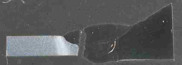
Metallographic examination indicated that the primary cracks typically followed the weld interface from the root toward the outside surface, but continued to propagate perpendicular to the surface as the weld interface diverged from its perpendicular orientation. The primary cracks were transgranular, with secondary cracks that were either transgranular or intergranular / interdendritic. No significant weld anomalies, such as lack of fusion, incomplete penetration, excessive porosity, or inclusions were observed for any of the prepared sections. The fracture profile was consistent with a progressive fracture mechanism, such as fatigue fracture.
The typical fracture morphology consisted of a rough, scalloped texture that appeared to coincide with the weld bond line. Microscopic fracture features typically consisted of a mixture of intergranular and transgranular features, with occasional microscopic striations. This fracture morphology was further evidence of a fatigue fracture mechanism.
Fatigue fracture requires a source of cyclic tensile stress above the endurance limit of the material. The results of this analysis indicated that the most likely source of stress at this location was from thermal expansion and contraction of the pigtail pipes and a disparity in the coefficient of thermal expansion between the P22 and Incoloy 800HT materials. A review of the system parameters indicated improper operation of the counterweight system, which had resulted in excessive stress on the pigtail connection to the catalyst tube.
In summary, the failure mechanism for the inlet pigtail pipes was fatigue fracture due to excessive cyclic stress on the pipes. No indications of weld anomalies or other significant material discontinuities were observed that would have contributed to the failures and the source of the stress was determined to be from improper operation of the thermal expansion compensation counterweight.
When a product fails through fracture of one of more components, determination of the fracture mechanism is a critical step in the failure analysis process. MEE technical staff’s expertise in fractography and understanding of the behavior of materials provided the data necessary to obtain our objective for this client.